


|
|
|
|
Copyright © 1989 CSA
Important notice: The CSA web site was re-designed in August of 2010. Some documents then available were out of date; so they were not included in the re-design and were not updated. This is one of those documents. Information about dates of posting and revision remains here, but there will be no revision of any kind after August, 2010.
This WWW document is based on the second printing of Computer-Assisted Drafting and Design: New Technologies for Old Problems; the first version was written in the spring of 1988 and finished in June. It was revised and reprinted in May, 1989, and last revised in April of 1996 before being posted here. Corrections, suggestions for additional information, and other recommendations for the next revision are welcome.
Footnotes are indicated by numbers in parentheses. Readers may call up the notes by clicking on the numbers.
II. Layers, Vectors, and Pixels
III. CADD - The Tool for Draftsmen and Designers
IV. CADD as an Aid for Scholars in the Humanities
VI. The Center for the Study of Architecture
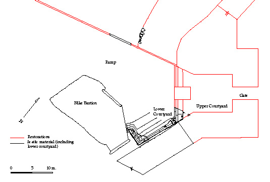
Fig. 1 - General View of the Propylaea in Athens, Plan View. Box indicates area of detail.
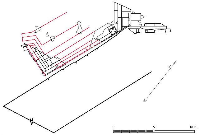
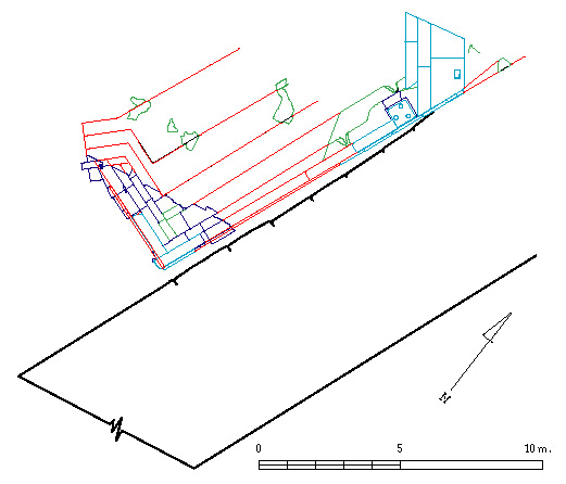
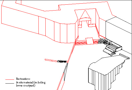
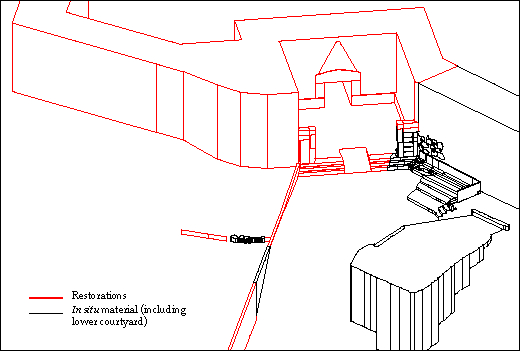
Fig. 3 - In Situ Material from Older Entrance to the Athenian Acropolis, View from NW.
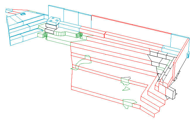
Fig. 4 - In situ Material. Elevation View.
Fig. 5 - In situ Material from Phase One. Plan View.
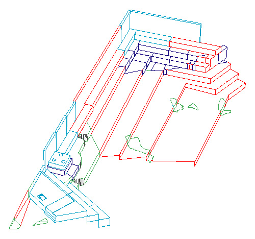
Fig. 6 - In situ Material from Phase One. Perspective View.
Fig. 7 - In situ Material from Phase One. Perspective View.
Fig. 8 - Reconstructed Entrance from Phase One. Plan View.
Fig. 10 - Reconstructed Entrance from Final Phase. Plan View.
Fig. 11 - Reconstructed Entrance from Final Phase. Perspective View.
Once upon a time, in the years called B.X., the hands of many who labored with the written word were covered with black and blue smudges, and strange white paint was considered among the most important modern desk accessories. In those difficult days Before Xerox people had to make multiple copies with carbon paper, and white correcting fluid was considered an absolute essential of the typing process.
Then along came Xerox. At first copiers were too big, too expensive, and too difficult to use for most. Only in very large offices were the giant machines to be found. Then, over time, the machines were made smaller, less expensive, and more reliable. More and more people discovered how helpful they could be, and finally they became indispensable, not only for big businesses but in the scholarly world as well. (Some cynics would say that copiers have made it unnecessary to read anything. Just copy it and put it in a file. But that's another story.)
Next came word processors. At first word processors were big, expensive, dedicated, single-purpose machines which were suitable only for large business organizations. But prices were reduced, and, at the same time, word processors became more flexible and easier to use. Eventually many people found that word processors brought significant advantages which were worth the costs. Scholars were relatively quick to see their advantages, and many have come to see word processors as indispensable.
Computer-assisted design and computer-assisted drafting machines (both often called CAD) have had a similar history. The first such machines were big, expensive, dedicated, single-purpose machines which were difficult to use and suitable only for large architectural and engineering firms. Although CAD prices have followed the trend and come down in price, the programs have not yet become widely used in the scholarly community, because they are clearly less central to the work of most scholars. However, CAD programs can be of significant importance to those who deal with three-dimensional objects, large or small, and the time has come for those who deal with such objects to treat these programs with the same enthusiasm which has been lavished on word processors.
These seemingly esoteric CAD systems can aid significantly the work of scholars who deal with objects of any kind. But the utility of these programs has not been obvious; the word has not been well spread. My aim here is to acquaint more scholars with CAD - its features and its capabilities - and to help to make the utility of CAD apparent so that the cycle here may also be complete.
The document has been divided into six sections. In the first section is a discussion of the background of CAD to give the reader some perspective, and in the second section are discussions of the few technical terms which are necessary to an understanding of CAD. A description of the features common to most CAD programs is in the third section, and it is followed, in the fourth section, by a discussion of the applicability of those features to the work of scholars in the humanities. The fifth section contains the technical information which is a starting point for a scholar who needs more knowledge of the details before looking for a system appropriate to his needs. In the sixth and final section is a brief description of the Center for the Study of Architecture and its aims.
The reader should be forewarned to check the date of this revision. The computer world changes so quickly that the information here may be out of date before it is six months old. Periodic updates will be made available in an attempt to minimize that problem.
There is no bibliography included here, because I have relied primarily upon information gleaned from my own experience with a variety of systems, manufacturers' literature, demonstrations, trade shows, and magazine articles. I would recommend that interested persons subscribe to the CSA Newsletter (see final section for details) and read computer magazines on a regular basis. General computer magazines contain articles about computer-assisted drafting and design programs more or less regularly, and there are magazines oriented toward CAD only (CADalyst and Cadence). They will provide more up-to-date information than books. The two CAD magazines will have more relevant information, but the general computer magazines will be intended for a broader range of readers.
Table of Contents
As early as the nineteen-sixties computer scientists began to develop computer-assisted drafting programs to assist architects in the production of large, complex drawings for major buildings. These programs provided automatic creation of standard shapes (lines, circles, arcs, dimension lines, etc.), and they gave architects capabilities for editing their drawings similar to those which word processors bring to the written word. As their name implies, computer-assisted drafting programs also automated the drafting process, driving specialized machines to produce drawings on a par with those made by a good draftsman - but in a fraction of the time. These programs made the creation process easier, permitted quick and easy adjustments to drawings, and automated the actual drafting.
At about the same time that computer-assisted drafting programs were becoming widely used in large architecture firms, computer-assisted design programs were appearing in the engineering design world. Engineering programs could create three-dimensional computer models of objects prior to production and display them on a monitor or on paper. With such programs engineers could carefully refine designs and far more accurately predict both appearance and performance.
There were two varieties of these three-dimensional design programs, differing in features according to their primary functions. One group of these programs - often called surface modelers - was intended primarily to offer product visualization so that appearance could be fully and accurately known before production began. The programs permitted the design of fully three-dimensional shapes which could be viewed in plan or elevation - or, more to the point for the designers, in perspective. Images could be manipulated so as to simulate the effects of various types of lighting, lights in different locations, varying surface reflectivity, and so on. The resulting lifelike images made it possible to predict far more accurately the final appearance of a product.
The other variety of three-dimensional computer-assisted design programs - so-called solid modelers - was intended to model the performance of an object rather than its appearance. These programs could model real-world objects, with mass and volume, simulating performance of parts under stress, showing multiple parts attached and working together, and so on. The solid modelers were designed with only a few of the visualization possibilities of the surface modelers, saving their computing power to model mechanical properties and performance.
Just as the two-dimensional drafting programs provided many aids to automate drawing standard forms, the three-dimensional design programs - surface modelers and solid modelers - provided similar aids, but the standard forms included three-dimensional shapes. Spheres and boxes, for example, could be generated automatically by these systems. Design systems also permitted the projecting or sweeping of two-dimensional profiles into three-dimensional surfaces.
Design programs were intended primarily to provide modeling on the monitor screen; so the quality of the drawings produced by these programs was generally not a major concern. The programs were to assist the designer rather than the draftsman. (1)
These CAD programs - both drafting and design programs - were designed to operate on large, specialized computers. They required special devices for drawing (called digitizers or tablets), though much of the information was actually entered from a keyboard as numeric data; special drafting machines (called plotters) were also developed. They often required expensive, high-resolution display screens as well. The whole package of computer, peripheral equipment, and programs could cost more than $100,000. Yet these programs were generally cumbersome to use, often requiring substantial time for training and an operator whose only job was to operate the CAD system.
When relatively powerful microcomputers (IBM personal computers, the many "clones," and Apple's Macintosh) became very popular in the early eighties, a few companies started to bring CAD technology to this price-sensitive portion of the computer market. The drafting programs were more easily transferred to microcomputers, and several drafting programs appeared on the market beginning before the middle of the decade. A few design programs appeared, but the demand was not as great, and these programs required greater computing power.
The lower prices of microcomputer-based CAD systems gave them a very large potential market, but CAD systems had to be easier to use to succeed in the broader marketplace; lengthy training sessions and specialized operators would have vitiated the cost advantages. Indeed, the systems which have been well received are much easier to use than their earlier, more expensive counterparts.
While drafting programs for microcomputers were gaining popularity, developers of larger systems began to combine the drafting and design functions - or at least to offer both in the same modular system - because they also had new, more powerful computers to work with. The best of the programs permitted the automation of drafting and the modeling of surfaces and solid objects. The combined programs - those which permit both automated drafting and three-dimensional modeling - are still called CAD programs (though they might better have been called CADD programs for computer-assisted drafting and design).
Microcomputers became significantly more powerful when IBM introduced the second version of the personal computer (called the AT), and programmers were able to modify complex and sophisticated CAD programs to operate on these personal computers. (2) These programs worked significantly better, i.e., faster, on third generation personal computers, those which use the Intel 80386 or Motorola 68030 chip, and new features could be added because of the power of the stronger chips. The introduction of yet stronger (faster) chips - the 80486, Pentium, Pentium Pro, 68040, PowerPC, and other so-called RISC chips - permitted continuing evolution of CAD programs for personal computers. The programs got faster, easier to use, and more powerful (though often the programs became so much more powerful that they sacrificed speed for power). The drafting and surface modeling features were brought together in these CAD systems for microcomputers in the late eighties, and solid modeling, though not as common, has been fully integrated with some drafting and surface modeling programs as well.
The evolution of CAD will surely continue. As computers become more powerful, programmers will be able to supply more features, and this process will apply to both personal computers and the larger, more expensive systems. We have already seen superb rendering programs for personal computers, and virtual reality programs for minicomputers are very much in the news. However, the process has long since reached the level necessary to provide powerful, reasonably-priced, fully three-dimensional CAD systems with important qualities for scholars in the humanities. It is those systems - the microcomputer-based CAD systems - which deserve our continuing attention and interest. Table of Contents
A few technical terms must be presented for the sake of the discussion to come.
LAYERS
CAD programs use the basic idea of the overlay - the idea that a drawing may be divided up into a number of constituent parts. Recognizing, however, that there need not always be a base portion of the drawing upon which all else depends, the program designers have given no part of the drawing priority; therefore, there is no base. Each part of the drawing is independently accessible, and each is called simply a layer not an overlay. Each layer contains whatever part of the drawing has been assigned to it by the operator; so the layers can be as logical (or as arbitrary) as the operator desires, and the drawing - no matter how simple or complex - may be broken up into as many parts as the operator wishes. The operator may select any combination of layers for display at any time. All will share the same scale and vantage point, but there is no single layer that must have been selected to serve as the frame of reference.
Using layers, an architect could draw separately the different systems of a building - each on its own layer - without redrafting those features which are common to many systems. Thus, he could draw a basic floorplan, showing only permanent walls on one layer, and on another the interior partitions, on another the electrical scheme, on another the plumbing plan, on another the heating diagram, and so on. To check for conflicts, the architect could display all layers at once, but the heating contractor could be given a drawing with only the floorplan and the heating diagram, and the plumbing contractor could receive a drawing of the walls and the plumbing plan. More important, the architect could change any given layer without worrying about the need to redraft an entire, complex drawing.
The flexibility provided by layers also provided creative benefits. If competing designs of one portion of a large project were under consideration, each could exist on its own layer as a part of the drawing and could be evaluated in relation to the remainder, yet nothing need be drawn twice. Working on an addition to an existing structure, the architect could draw the existing structure on one layer and the new additions on succeeding layers. (3) The possibilities are virtually unlimited.
PIXELS AND VECTORS
Although all computer graphics are simply organized pixels, computer images are created and stored in two very different ways. Some drawing programs create a kind of map of the computer screen. For each pixel on the screen there is a bit of data indicating the color which has been assigned to that pixel. These programs allow the user to draw very naturally with a mouse or stylus, and they can operate very quickly. However, the drawing is based on the individual pixels; it must be edited by altering individual pixels, not lines, circles, or other items in the drawing. Nor can such drawings be easily and accurately changed in size. Images from such a program are referred to as raster images, and the resulting images are sometimes called bit-mapped, though that term implies an absence of color.
Virtually all CAD programs operate very differently. Drawings are created and stored as groups of entities (lines, circles, arcs, etc.) with starting points (relative to a user-defined grid independent of the screen), orientation, and length; such lines are called vectors. The entities in these drawings are dependent upon formulae, not pixel locations. For these drawings to be displayed, the program must translate from the grid of the drawing to the grid of the screen. As a result, the programs operate more slowly. However, the drawings can be edited far more easily, because the objects in the drawing can be manipulated as objects, may be of almost unlimited size (regardless of how much of the total will fit on the monitor screen at one time), and may - indeed, must - be scaled when shown on screen or paper. Images from these programs are said to be vector-based.
The difference between the database of a drawing program and that of a CAD program is more than one of style. A drawing data file must have a data item for each screen location. On the other hand, a CAD file must have only the starting point, orientation, and length (or radius) for each entity. The result is a far more compact data file for a CAD drawing. Furthermore, the CAD entities are stored in the file as lines, arc, circles, and the like, with their positions in the users' grid system. Therefore, dimensions are always implicit in the data. A raster drawing, on the other hand, is only a record of screen locations; there are no implied real-world dimensions. Table of Contents
Contemporary computer-assisted drafting and design systems have many features which make them desirable to their principal users - architects and engineers. Not all features are equally useful to all users, but what follows is a list of the most important common features of CAD systems.
1. Automated production of standard shapes such as lines, circles, arcs, spheres, rectangles, squares, boxes, etc. All CAD systems provide automated drawing aids. The operator may give a start point, an angle, and a distance to draw a line; or he may give the start point and the endpoint; or he may select two existing points to be connected. These aids are more and more important as the objects to be drawn become more complex, and they are especially helpful when dealing with three-dimensional objects. In order to draw a stairway, for instance, the operator may draw the stairs in profile (a group of connected lines) and then direct the computer to sweep or project the profile for a given distance in the third dimension to create the stairway. This projection of a two-dimensional shape to create a three-dimensional object (often called extruding) is very helpful and a major time saver. Since the computer needs only a bare minimum of information to make an image, it is very efficient.
2. Editing of drawings - move, extend, trim, rotate, remove, etc. Most programs will permit the rotation of objects (around any axis), and most will allow objects to be reduced or enlarged. Virtually all permit objects to be moved, copied, or erased. Some programs will permit individual points of complex objects to be moved, and many will permit grouping objects so that they may be edited with one command.
3. Separation of material - using layers, as discussed above. CAD programs permit material to be drawn on separate layers so that the user may relate objects to one another in three-dimensional space (through the common grid) but keep them separate for display or drafting. Layers may be displayed (or drawn on paper) in any combination the operator selects, and most of the better programs allow nearly an unlimited number of layers.
4. Display of drawing parts selectively. The operator may turn layers on and off, change scale, enlarge only a small portion of a drawing, etc.
5. Use of colors to discriminate. The operator may assign different colors to material (by layer or object-by-object) for easy visual discrimination.
6. Automatic dimensioning. Nearly all CAD programs can automatically dimension an object (i.e., calculate the dimensions and place them on the drawing according to a predetermined format). Most such programs provide for so-called associative dimensioning. That feature links the dimensions to the object such that, if the object is changed, the dimensions are adjusted to reflect the change.
7. Recall of dimensions. Dimensions need not be displayed or drawn to be available, since most programs permit the operator to obtain the distance or angle between any pair of points or lines on command. Other information may also be obtained from the database on request.
8. Accuracy to any level. The user may enter data with whatever level of accuracy is desired. Objects may be traced from a scaled drawing, or dimensions may be entered directly as numbers so that they are exactly correct and are not affected by drafting skill or the limits of the drawing scale. Regardless of the method of data entry, however, dimensions are stored as actual numbers, not scaled approximations. (Some users may enter data as scaled numbers; it's possible to do so. But there is no advantage, and the user then loses the possibility of having the computer make calculations from real-world 1:1 dimensions. Using real-world numbers, full accuracy can always be maintained in the database and can always be retrieved on command. No matter what the scale of an individual drawing, the computer file remains always a 1:1 "drawing." (4)
9. "Drawing" in three dimensions - faithful recording of three-dimensional objects. Because CAD programs have been designed to provide three-dimensional modeling, they accept three-dimensional data readily. Some of the automated shapes are three-dimensional shapes, and virtually any shape can be projected or swept along a line or around an axis to produce a three-dimensional surface (or surfaces). In addition, the better programs will permit editing of individual points which are parts of the boundaries of surfaces, thereby making it possible to start with a standard shape and easily modify it into a non-standard shape that is a more accurate representation of an object. These programs permit three-dimensional data entry even when working with a view which does not show the third dimension.
10. Viewing from any angle - plans, elevations, isometrics, perspectives, even shaded images. Once created, the objects in a CAD drawing may be viewed from any angle, in any combination (using layers), at any scale, and with or without the foreshortening of a perspective view. The better CAD programs will permit the drawing to be made with hidden lines removed for a more realistic image and will even permit surfaces to be treated as true surfaces, with shading and with objects in the background hidden by objects in the foreground. (The more complex views with shading and hidden lines often take some time for the computer to generate; they require substantial calculation.) The programs which can provide shaded images may include extremely sophisticated rendering adjustments, e.g., choosing reflectivity, positioning light sources, adjusting ambient light, etc. Some can automatically provide an image of objects (with latitude, longitude, and orientation provided by the operator) as lighted by the sun at a given time on a specific day of the year.
11. Production of paper drawings. Anything on the screen can be put on paper. Images may be reproduced on paper at virtually any scale.
12. Storage of drawings on disks or tape. Information may be handled like any other electronic data and may be transmitted over a network. The data from one system, however, are usually not stored in a form readily accessible to another system; so translation routines are generally required to make data from one system accessible to another.
13. Linking drawings to text or data files. Most CAD program now have some way to connect information from data files to the drawings and/or to objects within the drawings.
14. Surveying from photographs. Some CAD programs permit photographs to be used to obtain survey data. Provided there are some surveyed points in the photo(s), it it possible to obtain good survey data - two-dimensional data with a single photograph and three-dimensional data with multiple images.
Table of Contents
The features of a good CAD program can be extremely useful to scholars in the humanities. Although some of the features have obvious value, there are others of equal, if less obvious, utility to those who deal with buildings, groups of buildings, ships, archaeological sites, or . . .
For a scholar involved in the production of any drawings.- whether they be of buildings, of objects, of ships, or of whole cities - the automated drawing features provide important benefits in speed and productivity. Similarly, the facilities for automating the actual drafting process make clear, accurate, and consistent drawings easy to produce.
Another important advantage of a CAD system is the ability to update information in a drawing, either by adding new information or by making alterations, without the tedious drafting and redrafting otherwise required. As one expands an on-going excavation, for instance, it is not necessary to produce new, smaller-scale drawings which can show the entire site; one need only add the new material and then let the computer produce a drawing at the required scale. In other cases, it may be necessary to alter the data after finding an error (either in the process of the work or long after, when material is restudied). The computer permits misplaced objects to be moved to their proper locations, mismeasured ones to be changed, or the data to be otherwise altered without reworking drawings from scratch.
The features discussed thus far - drawing, drafting, and editing - have value primarily to those who must enter and maintain data, i.e., the scholars who undertake the study of a monument or an archaeological site. Other features expand considerably the analytic possibilities and, consequently, the range of persons who find CAD helpful. These features are important not only to those who create and maintain the drawings but to all students of the material which has been found and drawn - archaeologists, art historians, historians, anthropologists, and so on.
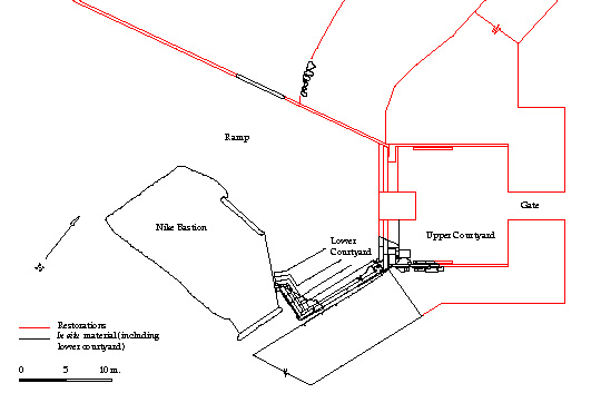
The most important of the features that assist with subsequent scholarship is data recall. CAD systems use the actual dimensions entered and only scale them for representing lines on screen or paper; so the originally recorded accuracy is always there. Furthermore, good CAD programs permit the database to be queried; so the accuracy of the original scholar is always available to the subsequent student as well. (The most accurate measurement available to the student is not, after all, the finest measurement made; it is the finest which can be recovered from the drawing or database. Given the range of scales of published drawings, the finest measurement available from a drawing will range from a few millimeters to a meter or more. Compare, for example, the drawings in Figures 1 and 2. Each is of a portion of the same material, but the scales are very different. The effect of scale on recoverable accuracy is enormous.)
INTRODUCTION
I. THE DEVELOPMENT OF CADD
II. LAYERS, VECTORS, AND PIXELS
Virtually all CAD systems have taken advantage of an idea which has been used in complex drawings for many years - transparent overlays. As the name implies, transparent overlays are drawings on transparent material which may be placed on top of another drawing. The base drawing is not on transparent material, but the overlay is. Placed atop the base drawing, the overlay will augment that base drawing so that there is a new effect, with the original showing through along with the drawing on the overlay. Such overlays were used in architectural work for years, with the basic structure of a building - the walls and structural supports - drawn on paper and the diagrams of electrical, plumbing, heating and air conditioning, and other sub-systems drawn on transparent overlays. The paper and transparent sheets had to be aligned by hanging all sheets on pins, hence the term pin-bar drafting.
Anything shown on a computer monitor - whether text or graphics - is simply a series of dots, some of which are white, some a color, and some black. The dots - called pixels - combine to create an image if the monitor is appropriately directed by the computer. The quality of the image, of course, is dependent upon the quality of the monitor and of the graphics hardware and software which instruct the monitor - different combinations provide larger or smaller screens, more or fewer pixels, and images in color, black-and-white only, or black-and-white plus shades of gray.
III. CAD - THE TOOL FOR DRAFTSMEN AND DESIGNERS
IV. CAD AS AN AID FOR SCHOLARS IN THE HUMANITIES
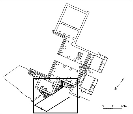
Fig. 1 - General view of the Propylaea in Athens, Plan View. Box indicates area of detail.
The use of layers for drawing different portions of the material from a site or structure provides another of the advantages for the broader group of scholars. A drawing for an archaeological site may have layers for building remains, hypothetical additions to those remains, small finds, pottery, coins, mosaics, etc. If necessary, the material may be divided into chronological or developmental groups within the larger groups of material types. But no matter how many layers there are, they are all part of a single drawing. One may view the drawing with all layers displayed (although the quantity of material would demand a very large scale in order to overcome the confusion of detail), with a single layer displayed, or with any desired selection of layers displayed. All of the material is accessible at once; the user need only decide what to view and what to suppress at the moment. Of course, the variety of material one scholar wants to see in combination is not necessarily what another wants. This is why the layers can be so important. Any scholar using the system may decide what material is important at a given moment and for given purposes. One can see what is important in relation to other objects, building remains, or whatever. Thus, the historian or art historian who is concerned about context can put CAD to good use, as can the archaeologist, anthropologist, or architectural historian. Figure 2, above, for instance, does not include the Propylaea so that the remains of the earlier structure are more clear.
The visualization features of CAD systems provide important benefits of CAD for the widest group of scholars. Understanding three-dimensional object(s) requires three-dimensional views - whether those views are in the mind's eye, on a computer screen, or on paper. So when the visualization features of a good CAD system are added to the use of layers, the result can be more than helpful; it can be crucial to real understanding. The visualization features do far more than save time or effort; they improve understanding. For any selected group of layers, not only plan views, but elevations, sections, isometric views, and perspectives may be produced quickly and easily. Hidden-line perspectives and shaded-image views may also be produced, though more slowly. Thus, the scholar may use various views of selected layers to improve understanding - choosing carefully the material which is to be seen and the angle from which to see it, making different selections of material (layers) as needed, and changing the point of view as new needs and questions arise.
This ability to combine large quantities of material in a single source, select portions of it, and view the selection from any angle is very important to any scholar who may have occasion to want a view of a three-dimensional object or group of objects - anything from a single building stone to all of the city of Rome before Nero's fire. Art historians looking for context and groupings, historians seeking setting, political scientists studying physical units of government, and many others would benefit from the use of good CAD systems with appropriate data.
Heretofore scholars have necessarily been restricted to two-dimensional media for publishing the results of their work with three-dimensional reality. Plans, elevations, sectional views, and so on provide a great deal of information, but they oblige the reader to conjure up his or her own mental image of reality. Drawn perspectives or isometrics come far closer to reality, but they must be from the point of view selected by the author - which need not be the point of view needed by the reader. CAD can overcome those limits inherent to the publishing process and bring to a scholar the talents of the most sophisticated artists and draftsmen, each working on command to produce the appropriate view for the best understanding. A computer screen may be a two-dimensional surface, but it can bring us very close to three-dimensional reality. (Of course, using CAD models in this way requires that scholars have access to the model and to appropriate software.)(5),
The entrance to the Acropolis in Athens
Some of the building remains and other material around the entrance to the Athenian Acropolis have been put into a CAD model, (6), and drawings from the system may help the reader to visualize more fully what the possibilities are. Included in the model are remains of structures erected between about 1200 B.C. and the time of the erection of the Propylaea, the grand entrance structure of the Periclean Age which was begun in 437 B.C. The nearby portion of the Bronze Age defensive wall, the surviving part of a Bronze Age terrace retaining wall, the Nike Bastion, the sixth-century B.C. retaining wall for the entrance ramp, and the outline of the Propylaea itself have been drawn. Figure 1, above, shows most of the material, including the Propylaea for reference; different line weights or different colors would be used in a paper drawing to distinguish between the remains of the older entrance and the Mycenaean wall and those of the Propylaea.
Different colors for making distinctions are more helpful - and may be drawn as well as displayed on the monitor - but duplication costs ususally prevent their use in publications. Figure 2, above, uses color to distinguish between the in situ remains of the older entrance (black) and some hypothetical restorations (red). This drawing shows a detail of the older entrance area, without the Propylaea and with some hypothetical material.
Figure 3 shows the area of the older entrance, but only the in situ material. Because the later material can be omitted, however, the view obtained here is much more helpful - in some ways more helpful than even standing at the site. There is no vantage point at the site that will permit such a view of the upper and lower courtyards at the same moment. (There are three versions of Figure 3, showing what can be done to label or shade the image in a rudimentary fashion. A complete rendering has not yet been produced at CSA.) Another view that cannot be obtained on the site today is shown in Figure 4; being an elevation of the wall of the upper courtyard, it is one of the most valuable views for understanding the area. But I can only produce it with the aid of the computer, since it is a view from the middle of the Propylaea.

As discussed above, combining material from different layers can often provide important aid to the scholar. For instance, Figure 3 shows a perspective view of the entrance area with all the in situ material, but we now know that the remains are from two separate phases of the entrance. Figure 5 shows the material from the first phase only, and Figure 6 is a plan view of the same material. None of these blocks had to be drawn more than once, but virtually all figures in each of three different entrances and can be included in the appropriate drawing on command. Figure 7 shows the same area from a different vantage point.
Adding the missing pieces to create a reconstruction of the first phase of this entrance yields Figure 8, a plan view and Figure 9, a perspective view. In both cases, the drawings could be generated by simply adding the appropriate layers to those visible.
The last phase of the old entrance involves rebuilding of some walls which had been demolished by the Persians and then repairing the entrance again after the repairs proved inadequate. The reconstruction of this phase can be seen in Figures 10 and 11, again a plan and a perspective view.
Since so little of the pre-Periclean entrance has survived, there is a great deal of material in these plans which is hypothetical, and the hypothetical material has been drawn without detail to make clear the difference between the true remains and the reconstructed additions; in the original booklet this was more important. For the Web drawings, since color can be used, color can show what is real and what is hypothetical.
The drawings presented have necessarily been ones of my choosing, not those each reader might have preferred had the system itself been at his or her disposal. My choices are fine for explaining the uses of CAD, but, for a scholar trying to understand the site and the various reconstructions, they would clearly not be as useful as views of his/her own choosing. That is one of the virtues of CAD; each user can select the views - points of view and layers included - that are necessary for his/her questions. Such a user could also selectively color material by layer or, for that matter, block-by-block to enhance understanding. Of course, that user could also obtain any dimensional information desired. In short, whatever I knew and included in the model can be learned by a user of that model.
One final point. I cannot illustrate here the connections between the model and the data tables constructed to accompany it. However, readers should understand that it is possible to select any in situ block and obtain information about that block - its name, material, remarks about cuttings, and the like. It is also possible to learn what layer any item in the model is on and what the characteristics are of that layer. Finally, there are notes about specific areas, blocks, and features. Icons in the model indicate the presence of notes, and users may, by selecting the appropriate icon, read any note. The connection of these data tables to the model narrows even further the gap between what I know and what I have recorded. Table of Contents
A full consideration of the problems and potentials of CAD must, sooner or later, include some discussion of the equipment and the programs which will be used. For some readers, this section will seem inappropriate, but the nuts and bolts will be very relevant to others.
Hardware
Computers seem to change - generally for the better - almost by the hour. More powerful, more economical, and faster processors are regularly developed; so smaller and less expensive computers become capable of doing more and more complex work. Given the particularly demanding nature of CAD systems this process has been very important, yielding personal computers powerful enough to satisfy those demands.
The IBM and IBM-compatible computers which use Intel chips are very powerful and can easily handle CAD work. The same is true for the Macintosh line from Apple. In general, faster, stronger processors are more important for rendering than for CAD work. When working on a model, the user is normally the bottleneck, not the computer. There are times, though, when the speed of the computer can be very important, especially if the operator must wait for computer operations to be completed in order to continue building the model. Such interruptions can be very disruptive.
Many computers more powerful than the personal computers discussed above are available for running CAD programs, but such workstations or minicomputers are generally more expensive. Since it is important that CAD be available at a reasonable cost, this discussion has been and will continue to be limited to the more reasonably priced personal computers and CAD systems which can run on them. It should be clear, though, that more powerful computers will run these very demanding programs better (faster).
The choice of machine to be used for a project must depend upon individual preferences - particularly if choosing between an IBM-compatible and a Macintosh. Price, of course, must also be considered carefully. The choice of machine is also very much dependent on the CAD program to be used. In most cases, the CAD program is more important and should be selected first.
Operating Systems
The programs most people are familiar with are called application programs. They permit a user to perform a task; a CAD program is an application program; so is a word processing program. But these programs need operating systems, underlying programs which form the base upon which the application programs operate; indeed an application program must be written to work with a specific operating system.
Operating systems handle the routine tasks for application programs and make communication between user and processor easier. Operating systems control access to peripheral devices, memory management, timing, and a variety of other tasks. Macintosh computers use a proprietary Apple operating system; IBM and IBM-compatible computers generally use MS-DOS, with or without Windows. IBM's operating system for PCs, OS/2, has been more or less orphaned by IBM; so it is no longer a viable option. The new Windows 95 operating system from Microsoft offers some advantages, but Windows NT, also from Microsoft, seems a much better choice. Windows NT does require more memory and disk space than Windows 95.
UNIX, the minicomputer operating system, can be used on PCs, but it has never managed to be a real force in the PC marketplace.
Data Entry Options
Various options for entering data exist: electronic theodolites, keyboards, digitizing pads, mice, scanners, and close-range photogrammetric systems.
1. Entering data directly from electronic theodolites. Advances in surveying equipment have made it possible to use electronic theodolites (total stations) to make measurements and to feed them directly into a computer for inclusion in drawings. This provides maximum accuracy and efficiency (at a rather high price). However, most total stations do not format the data as archaeologists would prefer (total stations are made for surveyors); so they do not fully automate the data-gathering process. They do however, make it possible to by-pass many steps and, in the process, to omit several opportunities to introduce errors.
2. Entering with the keyboard. The keyboard provides another accurate means of data entry. The actual measurements taken may be directly entered, and there is no loss of accuracy due to mechanical imprecision. This method can be slower than those mentioned below, but it is faster if the data have been collected with such an entry process in mind.
3. Entering with a digitizer. Digitizers are simply electronic drawing boards which feed the location of the "pencil" to the computer for translation to digital form. For transferring paper drawings - by tracing - the digitizer works very well. It is also convenient for drawing material which has not been accurately measured but can be drawn by eye. At best, however, the digitizer cannot provide the level of accuracy of keyboard or direct theodolite entry, and, since one is dealing with a two-dimensional surface, like a drawing board, the data entry is limited to two dimensions with the third held constant or entered from the keyboard. (Direct digitizing of objects with three-dimensional digitizers provides very good accuracy, but three-dimensional digitizers are complex and rather expensive.)
4. Entry with a mouse. The mouse is, for all practical purposes, a less accurate digitizer. It can be used for drawing by eye, but not for entering material with great accuracy. (Accuracy can be improved with a mouse - or a digitizer - by activating a constant location readout so that the x- and y-coordinates of the current location are always shown on the screen. This is an option with most programs, but the process becomes very slow and tedious.)
5. Entry with a scanner. Scanners provide quick and easy transfer of paper drawings into the computer. The machine "reads" the drawing and converts the image into digital information. Unfortunately, scanners transfer data as individual points (usually based on a grid of 1200 x 1200 points per inch or fewer) not lines and vectors. Scanned images can be very useful in drawing programs, but the data must be translated into vector-based data to be useful in a CAD system, and the resulting data file will be much less accurate and far larger, even after translation, than a CAD file specifying the same data. There are programs for tracing scanned images and turning them into vector graphics, and it is also possible to trace a scanned image on screen with some CAD programs. (See CSA Newsletter, Vol. 8, no. 4, February, 1996, "Drawing Profiles - Another Method" for a discussion of these methods.)
6. Close-range Photogrammetry. Photogrammetry permits accurate 3-dimensional measurements to be made from appropriate photographs. Close-range photogrammetry applies the same mathematical principles to photographs that can be placed on a digitizer and used to survey. In the past, the technology has required carefully controlled photographs and extremely expensive computer equipment to determine 3-dimensional points. New close-range photogrammetry programs, however, can provide good accuracy without such carefully controlled photographic work, though still at rather high cost (comparable to that of total stations). (See CSA Newsletter, Vol. 3, no. 2, pp. 1-3, "Accurate, Efficient Surveying with MR2 Program, " and, pp. 3-4, "Using the MR2 Program and Tolerating Frustration, " for a description of an experiment with a photogrammetry system from Rollei.)
7. Single-photo photogrammetry. Measuring in three dimensions requires multiple photographs of the area to be measured. It is possible to do similar work with a single photograph, but the photograph must be of a plane, a single flat surface, and only the points on that plane can be transferred into the CAD system (See CSA Newsletter, Vol. 8, no. 3, November, 1995, "Single-Photo Photogrammetry at Pompeii in 1995" for a discussion of this system.)
Monitors
There are many kinds of monitors (and the associated hardware to "drive" them) that work well with CAD programs. Monitors vary according to image resolution and whether they show color, black-and-white with shades of gray, or only black-and-white. Color is a necessity in the analysis phase of work but may not be needed for data entry (though some programs work only with color and, in general, black-and-white has become rather rare). With black-and-white (with or without added gray tones) one cannot easily distinguish between and among more than two or three layers which are displayed simultaneously; so some of the potential of a CAD system is sacrificed if color is not used.
Monitors vary widely in terms of image resolution, measured by the number of points which can be separately addressed by the computer (pixels). The number ranges from about 75,000 (a television image) to more than two million. Obviously, the greater the number of such points, the more lifelike the images may be. For most purposes, the monitor standard sometimes called SVGA (800 x 600 discrete points) is a minimum, and a monitor that displays 1024 x 768 pixels is now taken to be desirable for CAD work; some would demand 1280 x 1024. Most would recommend a 17-inch monitor as a minimum. Beyond the SVGA level, additional hardware requirements (specialized graphics boards and the monitors) drive prices up quickly. For good shaded images, however, the extra cost of more specialized equipment is inescapable.
Monitors also vary in terms of the frequency with which the image on the screen is refreshed; that is, the signals need to be sent repeatedly to the monitor to keep the pixels lighted. Fewer signals per unit of time mean a less stable image. Most would recommend a monitor that can, at the least, display the image with a 72Hz refresh rate or higher, but the actual rate used will depend on the graphics card in the computer.
Data Output
Most CAD systems are set up to make drawings on either standard printers or plotters. Good results may be produced with a laser printer or an ink-jet printer, and some high-resolution laser printers can produce excellent results. They are limited as to paper size, though.
Pen plotters, mechanized drafting machines which can produce line drawings (in black-and-white or color, with felt-tipped or standard drafting pens) on standard drafting paper provide better line drawings than laser printers. Very large drawings can be produced with pen plotters (nearly any length on 48-inch-wide paper), but the number of colors and the choice of line weights are limited. Although plotters are very accurate, they produce line art only. They will not duplicate shaded-image views. Plotters have become nearly extinct because of the rise of ink-jet printers and laser printers. In fact, since we rarely publish large drawings or color, laser printers are probably the best all-around choice. Large plots can be obtained from specialized graphics suppliers when needed, and laser prints up to 11 in. by 17 in. can be produced in the office. (The same printer can, of course, be used for standard office printing.)
Inkjet printers have become the standards for CAD work. Inkjets offer advantages in noise, reliability, and color repeatability. They are also better for printing renderings or other filled-color images.
It is also possible to reproduce the shaded images photographically. The results can be very good. Sophisticated equipment is available for the purpose, but one may also simply photograph the monitor screen for an acceptable image. Practice is required. (7)
Programming Languages
Many CAD programs permit the user to add mini-programs (often called macros) to the system in order to make certain repeated processes easier. This is done by making the programming language available and by building into the programs certain facilities to permit the functioning of the macros. Since academics using CAD systems need to record existing material - a process very different from the design process for which the base program was created - this feature can be a valuable one.
Selecting appropriate cadd programs
There are many CADD programs for microcomputers, and it is tempting to compile a list of them here. However, the programs change almost daily as the field attracts new entries and rejects unsuccessful ones. Therefore, it should be more helpful to provide a discussion of the features which are most important in the evaluation process and then to discuss a few of the better-known programs.
It is pointless to examine programs for hardware you do not own. So, if you have hardware that you expect to use, you may want to limit your search to programs that can run on the hardware you already own. However, even then it would be wise to explore the programs for other platforms. If specific needs cannot be met with software for your current hardware, it may be better to wait or to purchase new hardware.
If you may need to use more than one platform, of course, you will want to examine programs that can operate on all the platforms you expect to use. Not many programs will operate on more than two different platforms, but there are some that will.
The single most important feature of a CAD program for scholarly use is full genuine three-dimensionality. Many programs claim three-dimensional features but do not deliver fully. The scholar's needs are for full visualization of real objects; so surface modeling is the necessary minimum level of sophistication. The objects are not idealized ones; so the program must not be limiting, and the three-dimensional features should be a part of the core program, not add-ons requiring the user to create a two-dimensional model, switch to another program, and then add the third dimension. (8)
Having access to the programming language for creating macros is extremely desirable.
Many programs have associated database management capacities. This permits objects to be linked directly to database information - excavation units, individual objects, even personnel. This is a very valuable feature.
The actual data on which the drawings are based, the information about dimensions, can only be accessed from the program itself; the operator must be able to extract such data. Surprisingly, however, a few programs do not permit the operator to obtain coordinates of any specified point or distance between points.
Visualization features, of course, are very important. Programs should provide hidden-line drawings and modeled surfaces, with shading. It should be possible to select any point for perspective views.
The hardware demands of programs should be carefully considered, but, in general, the better the equipment, the better the program will operate. There are some programs which demand specialized processors and should therefore be carefully assessed. Others may offer very few options for peripherals; that should be taken into consideration. In some cases, less expensive equipment will be specified as acceptable; a potential user should examine carefully the speed of operation which may result.
Ease of use is too easily overlooked by the first-time buyer of CAD systems. No system should be considered which has not been used in a demonstration setting and found to be acceptable, and no purchase should be made without using at least two systems in a demonstration. (9) There are important differences in operation which may seem trivial until one actually tries to use a system.
Some otherwise excellent systems limit the user to two-decimal-place accuracy, and others limit the size of the overall model to a specified number of the base units, whether they are feet or millimeters. These limits should be checked.
Many programs now permit the drawing of splines and Bezier patches. Splines are computer-generated curved lines which are fitted to predetermined points. (The operator specifies the points; the computer creates a smooth curve to connect them.) Bezier patches are planar surfaces on which a grid is superimposed. At any intersection of the grid the planar surface may be pushed or pulled in the third dimension (relative to the plane of the surface); very complex surfaces can be modeled. Both these rather arcane features can be helpful. (Splines which can be projected or swept in the third dimension are also helpful for creating complex surfaces.) Especially valuable is the non-uniform rational B-spline, a continuous curve that fits any number of data points in a sequence. (Other types of splines may not actually pass through all data points in an effort to retain the continuous curve.)
Some programs permit the computer screen to be divided into portions, often called windows, each with a different view of the object(s). This can be a very helpful feature, especially for operators who are accustomed to engineering-style drafting, with front, top, and side views all on one drawing. For others, that feature may not be important or may even be confusing.
It should be obvious that the strength and history of the company which produces the program may be important. There are excellent programs which have come from small and obscure companies, but one needs some confidence that the program will be supported for years in the future. In addition, some of the companies which produce CAD started designing CAD systems for larger computers and have brought their systems to the personal computer market; others started designing their CAD for personal computers from the beginning. There are inevitable differences. Companies which began with CAD on larger, more expensive computers are accustomed to larger corporate customers; so they tend to assume that training will be purchased along with the CAD system. Therefore, their instruction books are often less helpful (to say the least), but their willingness to offer help over the telephone may be greater. Similarly, those companies are likely to support a more limited range of peripheral equipment, because their traditional customers will have regularly purchased complete systems at once. On the other hand, those programs were designed for demanding professional users; so they may be faster and have more features.
An important difference from one program to another is the quality of the instructional materials. Be sure to check the manual which will be supplied for such things as indices, avoidance of jargon, completeness, and so on.
Finally, no program should be selected if it will provide only a proprietary file format. That is, the data file created should be useable in other programs, or it should be possible to create a file in a format that can be used by other programs. Most CAD programs, in fact, write files in an open exchange format called .dxf; however, not all such files adhere fully to the standards, especially as regards the third-dimension. Care must be taken to be sure that a model, once complete, can really be used by others.
Some Specific CAD Programs
My own experience with CAD began with a two-dimensional program called Caddraft, which was immediately helpful, but very limiting. As a result of the experience with that program, I continued working with CAD but changed to AutoCAD, then the most popular of the two-dimensional CAD programs for personal computers. It was far more useful and proved the value of CAD, but at the same time proved the importance of true three-dimensional capacity, which AutoCAD then lacked.
A careful search for an appropriate three-dimensional program which would operate on a microcomputer followed, and the ARRIS programs from Sigma Design, Inc., were chosen. This group of programs was not perfect, but it appeared to be the best compromise at the time it was chosen. Its benefits and features may be instructive.
ARRIS was a fully three-dimensional program, with all the shading and perspective-view features one should expect. The shaded-image views in particular seemed to be the best available without far more expensive peripheral equipment. It required an expensive, specialized graphics board with at least a multi-synch monitor for shaded images (and an even more expensive board and high-resolution monitor for better shaded images), but it would do other tasks with less expensive graphics boards.
The program had an accessible language, and the operator could customize commands and, to a degree, the screen. ARRIS also had excellent features for requesting information from the graphics database (x, y, z coordinates, distance between points, etc.). There was also an associated database manager.
The ARRIS system ran under the XENIX (a variant of UNIX) operating system at the time it was used at CSA. So there were some difficulties that might not have been noticed in other systems. More important, the ARRIS programs supported only a few digitizers fully enough to permit the user to trace existing drawings. The entry procedures were excellent for keyboard use, permitting relative or absolute data points and - a very important feature - permitting temporary rotation of the x-y axes for entering data. Since the operator may enter data directly in an isometric view, the three-dimensional entry is very straight-forward, and simultaneous multiple views on the screen were not needed.
The ARRIS programs have been updated and now run under Windows, but they have not been used at CSA for some years. We have no experience with the current software.
When the 3-dimensional version of AutoCAD, called Release 10, was introduced for DOS machines in October of 1988, it was tested at CSA. It was then adopted as the program of choice for a variety of reasons, as had been expected.
AutoCAD is available widely (and offered at an academic discount), as is training for using it. The program permits the modeling of three-dimensional surfaces with several techniques, including splines, and it has thorough editing features for those surfaces. It supports multiple windows (called viewports) and will even permit successive points to be picked from different windows, a feature which can be very helpful. Another desirable feature permits the user to define his drafting plane as any three-dimensional plane (a step beyond the rotating of x-y axes). AutoCAD has an accessible language (AutoLisp) for creating customized routines, and completely personalized menus are not difficult to create (programs in C can also be used with AutoCAD). AutoCAD's strengths are very important, including relatively good documentation, support of almost all possible peripherals, wide availability, and support of many different computer types. The current version of AutoCAD is available for various UNIX machines, DOS, Windows, and Windows NT. The next-to-last version is available for the Macintosh as well, though continuing support for the Macintosh has stopped. The fact that AutoCAD can be used on so many different computers/operating systems is very important, but it is even more important that all files created by AutoCAD, whatever the original computer, can be exchanged from one machine to another without translation. Therefore, scholars may share their information at a level previously assumed to be impossible. (I was much more comfortable recommending AutoCAD when there was a Macintosh version; however, I know of no other program to recommend in its place.)
Some other programs deserve mention as well. Microstation is an excellent program, with superb drafting capabilities. Its multiple windows make drafting easier. Microstation runs under MS-DOS, Windows, UNIX, and the Macintosh operating system. It has two important drawbacks. The maximum number of layers per drawing is 63, and the layer names are limited to 16 characters in length. AutoCAD, by comparison, can have thousands of layers in a drawing, and the layers may have very complex names. (Complex names are very important when constructing a model. See CSA Layer Naming Convention.)
Although several other programs also deserve consideration for individual projects, the advantage of a single standard is such that AutoCAD must be very strongly recommended. It is now a fully three-dimensional program, has all the drafting features needed, supports a very wide variety of equipment, and is available virtually everywhere. Other existing programs, improved programs, or new ones may have advantages, but, for at least a time, it is unlikely that they will be sufficient to overcome AutoCAD's benefits of being nearly ubiquitous and the standard by which others are judged. Most important, if AutoCAD becomes the standard used, data can be exchanged as easily as mailing disks from scholar to scholar. (Some other CAD programs have begun to use AutoCAD's own file format; so that problem may be losing importance.)
Specific Hardware Recommendations
Assuming the use of AutoCAD, some specific suggestions concerning hardware can be made, but these recommendations should be taken as guides only. Equipment changes so rapidly that one must be flexible in order to find the best combination of performance and price. Furthermore, the best solution is to put the program to work on hardware which is already owned, even if it is not the most desirable equipment for the task. Once one has operated the system for a time, one can better judge the importance of the major features - speed, convenience, display clarity, etc.
For those who prefer the IBM-compatible world, there are several possibilities, and there are many magazines which review products and show prices for comparison shopping. The core of a system should be a Pentium or Pentium Pro processor. AutoCAD will operate on 80386 (with coprocessor) or 80486 machines, but the Pentium is better and the Pentium Pro better still. The clock speed of the machines will have a dramatic effect on price; one should operate different machines (running AutoCAD) to determine the importance of speed for oneself; in general, the faster one can afford, the better, but the very fastest current model will usually involve a substantial price penalty. A RAM cache should be built into the machine to provide faster operation. There are many brands of computer which might be recommended, and it is even possible to have a computer assembled at a local computer store according to individual requirements. That can be the best choice for those who want a machine with specific features. (Laptop computers can be used for CAD in the field, but one is probably best advised to use a minimum level laptop in the field and better equipment in the lab. If a laptop must serve in both places, it should be possible to add higher-resolution monitors with ease.)
A good system should have at least 16 megabytes (MB) of random access memory (RAM), a 1 GB hard drive, two serial ports, and a parallel port. A better system would include 32 MB of RAM and a hard drive of 2 GB or so. If rendering is to be done, 32 MB of RAM and a 2 GB hard drive would be considered necessary.
The monitor and graphics board for an IBM-compatible system should have resolution of at least 1024 x 768, with at least 256 colors. The buyer must be certain that the graphics card chosen has the necessary software (drivers) to operate the programs which will be used with it and that the card is compatible with the monitor selected. Higher refresh rates (the rate at which the electrical impulses to the monitor are sent) reduce potential eye strain, and the 72 Hz rate is considered a minimum. More colors are necessary if renderings are done.
For those interested in the Macintosh world, a Mac 8500 or 9500 would be the machine of choice today. It should have at least 16 MB of RAM and a 1 GB hard disk; 32 MB of RAM would be preferred.
Regardless of the computer chosen, a good digitizer should be part of a complete system. Although a mouse can be used, a digitizer is a must if drawings are to be traced or if close-range photogrammetry is to be done.. The digitizer needs to be as large as the largest drawing which will regularly be traced (though drawings can be traced in sections). A multi-button puck should be used, one with as many buttons as possible, since the buttons can be programmed to issue commands directly, resulting in the saving of a great deal of time. There are also models that can be rolled up to be carried along with a laptop computer.
The plotter chosen should be capable of making drawings of whatever size will be needed. Newer machines using inkjet technology are the more popular plotters now; in any case, plots can also be made by service bureaus. Thus, one might choose to purchase only a small plotter or to use a standard laser printer to handle most needs and send a file out to be plotted at a service bureau when larger sizes are required.
Depending on the level of hardware chosen and the discounts available, the total hardware cost will range from about $5000 to ?? - the sky really the only limit. Table of Contents
The Center for the Study of Architecture (CSA) was established to create, maintain, and make available to interested scholars/students an archive of significant architectural monuments in CAD form. CSA will engage in, assist with, and sponsor work to study architectural monuments so that they may be added to the database.
In order to accomplish that basic purpose, scholars at CSA will encourage excavators to use CAD so that newly studied architectural material may be directly accessible to scholars through CAD systems. Personnel from CSA will also work with other scholars to encourage the use of CAD in appropriate areas and, in general, to make apparent to all scholars the potential benefits which the use of CAD systems may bring to their work.
In order to further the aims of CSA - and, at the same time, those of other scholars - personnel from CSA are prepared to assist in the examination, evaluation, and selection of CAD systems and related equipment or programs for use by other scholars. Training in the use of CAD and related surveying techniques is also available from CSA, and personnel are available to put on seminars covering the entire range of issues surrounding the use of computer technology in field work. In addition, CSA publishes the CSA Newsletter to provide up-to-date information about applications of technology to the work of archaeologists and architectural historians. This booklet is a part of CSA's assistance to interested scholars, but more individualized help is available on request. Inquiries should be directed to: Center for the Study of Architecture, Harrison Eiteljorg, II, Director, P.O. Box 60, Bryn Mawr, PA 19010 (director@csanet.org). Please note that, as of May, 2000, the CSA Newsletter is available only on the Web.Table of Contents
NOTES
1. Some of the CAD programs were also designed to communicate directly with computer-controlled mold-making equipment so that a mold for a product could be made directly from the design. This process is often called computer-assisted manufacturing and has resulted in the common abbreviation CAD/CAM for the combination of computer-assisted design and manufacturing. Return to text at note 1.
2. Along with single-purpose CAD systems and combined drafting and design systems, there are hybrids which offer different combinations of features. Some provide very limited three-dimensional features. (Believe it or not, they are sometimes called two-and-a-half-dimensional programs.) There are also programs which deal with three-dimensional objects accurately - but only their edges, not their surfaces. Such programs provide so-called wire-frame images, but they cannot show shading or surface features. Return to text at note 2.
3. It should be made explicit that drawing layers have no relationship to excavation layers or strata. The term, indeed, has no necessary relationship to physical location whatsoever.Return to text at note 3.
4. Since the computer stores dimensions without scaling them, the level of accuracy to which one has measured - and the accuracy recorded in the CAD file - is not subject to loss due to the scale of any particular drawing. Therefore, measurement and survey accuracy should be of the highest order. Return to text at note 4.
5. The use of the term model here is not accidental. The result of a thorough recording of a building or excavation with CAD is a three-dimensional model, at full scale, of reality. It is not a drawing but a model that may be viewed from various angles and with various combinations of material chosen. Each view is itself a drawing, whether on screen and ephemeral or on paper. But the data file is a model capable of producing an infinite number of individual drawings. Return to text at note 5.
6. I am not here attempting to argue the fine points of the restoration. There are reasons for the dimensions, and the hypothetical material has full dimensions, but this is not the place for a discussion of the evidence upon which the reconstruction shown has been based. Return to text at note 6.
7. The drawings reproduced here were produced with Adobe Illustrator and Photoshop. In the original booklet, a Hewlett-Packard plotter was used. Were the booklet being produced today, a high-resolution laser printer would be used, assuming color would not be affordable. Return to text at note 7.
8. Initially, it had seemed to me that solid modeling should be the ultimate aim. However, work with the older propylon has demonstrated that surface modeling is more appropriate for archaeological and architectural history work, because it is so rare that one really knows enough about a block or object to make an accurate solid model. Rather, one has some surfaces which are visible and other surfaces which are not.
The major advantage of solid modeling over surface modeling is the ability to obtain physical characteristics such as weight or carrying capacity of blocks and beams. One can still determine such properties with a mixed model, one with some solid-modeled blocks or beams and some surface-modeled items. Return to text at note 8.
9. In most demonstration settings, the prospective purchaser has little opportunity to operate the system and must be content to watch a well-trained and experienced operator. If possible, however, one should use the system oneself. Some systems will seem intuitively "correct;" others will seem to demand difficult operating procedures. Return to text at note 9.