
|
Harrison Eiteljorg, II
Readers of the CSA Newsletter will be accustomed to my oft-stated concerns about the way AutoCAD,® - for that matter, any computer technology - is used in scholarship. My regular discussions of layer-naming systems in AutoCAD are probably the best examples of that. The concerns about the ways scholars should use AutoCAD sometimes result even in suggestions that sophisticated capabilities built into the software be avoided because of unexpected problems with those capabilities. The article of some years back about linked data tables, for instance, suggested that the sophisticated linkage of CAD objects and tabular data information provided by AutoCAD should not be used by scholars ("Linking Text and Data to CAD Models," Harrison Eiteljorg, II, XIV.3 [Winter 2002]: http://csanet.org/newsletter/winter02/nlw0201.html). An alternate was proposed. That concern about sophisticated features can make me seem a bit of a troglodyte, but I am more concerned about how well a resource may be used, both now and in the future, than in the use of the most sophisticated features of programs that are not, after all, developed with scholarly users in mind. This long introduction leads to the assertion I will make and try to support here - that AutoCAD users should avoid the use of blocks and cross-references files (xrefs). I have examined the use of multiple files within a single CAD model in a previous Newsletter article, ("Multi-File CAD Models," Harrison Eiteljorg, II, and Susan C. Jones, XV.1 [Spring 2002]: http://csanet.org/newsletter/spring02/nls0203.html).
Readers should be aware that the experiments described here have been conducted with AutoCAD 2000, not a later version. An experiment with the latest version will be undertaken shortly, and a report will follow.
Blocks seems to be among AutoCAD's most useful and innocuous features. Any objects can be modeled, selected, and declared to be a block. The entire block may then be inserted into a drawing on any layer at any location or orientation without re-modeling. The problems for scholars lie in the way blocks function after being drawn and inserted.
To examine and illustrate the difficulties I performed a simple experiment. (I did this work originally on my MAC, running AutoCAD under Virtual PC® but then repeated the work on a PC to be sure that there were no oddities introduced by running AutoCAD under Virtual PC.)
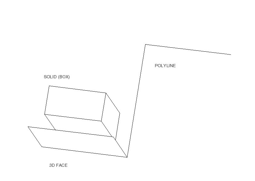
1. I made four blocks, each consisting of a polyline, a 3D face, and a solid. The four blocks were identical in terms of their content. (See Figure 1 for a 3D view of the block.)
2. Two of the blocks were created on Layer 0 and two on Layer 1.
3. All the entities in one of the blocks on each layer were given a specified color, and the entities in the other block on each layer were given AutoCAD's "bylayer" color designation, making the color of the entities to be used in the block dependent on the stated color of the layer. As the blocks were created, they were named according to their characteristics, thus 0bylayer (created on layer 0 with entity colors assigned as bylayer), 0red, 1bylayer and 1blue.
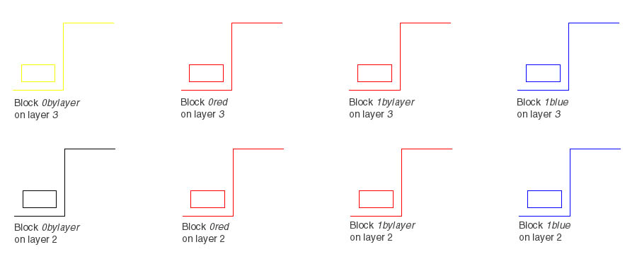
4. One of each of the blocks was inserted on Layer 2 and on Layer 3. The starting condition at that point, showing the blocks on layers 2 and 3, is shown in Figure 2. (Layer 2 was colored black, and Layer 3 yellow.)
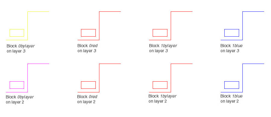
5. The color of Layer 2 was changed to magenta via the dialog box for layers.
6. The colors of all the blocks on Layer 3 were changed to green, using AutoCAD's change property (chprop) command. The result is shown in Figure 3. Note that only one block (0bylayer on Layer 2) has actually changed color, though the command to change the colors of the layers and the command to changes the colors of all the blocks seemed to work normally; there was no error message or other indicator of a problem.
7. Printouts were made, showing the same colors as the screen views.
Note the following:
1. All blocks except 0bylayer always show in their original colors, whether they have only been inserted as blocks or have had their colors changed, either by changing the layer's color or the block's color.
2. Changing the color of the layer on which the block 0bylayer has been placed changes the display color of the block on that layer, but changing the color of the block directly does not.
3. Changing the layer color did not change the display color for the blocks created on Layer 1.
4. Not clear in the illustrations is the fact that those blocks whose color was explicitly changed to green are declared to be green in all cases. In answer to queries, AutoCAD declares each block to be green, though not one actually is green.
5. Also not clear in the illustrations, AutoCAD declares layer colors changed and the blocks to be colored by layer, even when the blocks' display colors are unchanged.
6. Printouts show the colors as on screen, not as reported by AutoCAD.
In addition, the blocks that were created from items on Layer 1 (1bylayer and 1blue) disappeared when Layer 1 was frozen, even though the blocks were on Layer 3. This is, in fact, a general problem. A block made from objects on any layer other than Layer 0 will be displayed only if BOTH the layer on which the block was made AND the layer on which it was inserted are thawed. This is not an insurmountable problem, but it does require that blocks be made on Layer 0 and only Layer 0 if a good layer-naming system is to be useful.
It might be argued that making blocks on Layer 0 from objects assigned the "bylayer" color choice remains a reasonable use of AutoCAD. That assumes, however, that nobody would every want to assign a color to a block independently of the color of the block's layer. However, printouts, in my experience, often require just such color changes; so I do not believe that to be a good, safe approach.
Since blocks can be exploded - turned back into the items from which they were made - it would seem possible to use blocks and then to explode the blocks so that they no longer act like blocks. Unfortunately, when exploded, the objects return to the layer on which they were first modeled, disappearing from the layer on which they were inserted. So, if a block consists of objects originally modeled on the layer where the block will be inserted and the block is eventually exploded into its constituent elements again, all iterations of it may, once exploded, function as well as any other modeled objects. The requirements, however, are such that I believe it better simply to avoid the use of blocks altogether. If an object or group of objects can conveniently be made into a block and inserted many times, it seems to me that it is preferable to make the object or group, copy it, and paste it into its new positions as required. The result is the same in terms of the appearance of the drawing, and the layer problems -- as well as the problems with printing using the correct colors and line weights -- are avoided.
Cross-referenced AutoCAD files, called xrefs, are extraordinarily helpful for architects working on complex projects involving many different specialists. They are somewhat similar to blocks in that they are inserted, scaled, and oriented in a base drawing, and they are attached to a specific layer, not to the model generally. Unlike a block, though, the external file can be changed repeatedly, and each time the base file is opened the latest version of the external file will be there as well, in the proper position and orientation, and at the right scale. Therefore, while one person works on the electrical system (in its own AutoCAD file), another may work on the plumbing for the same structure (in another AutoCAD file). Neither conflicts with the other while working, but the results of both can be combined with the other portions of the design by treating each as an xrefed file attached to the basic structural file -- or whatever file is used as the base file.
Instead of a single file with many parts on many different layers, a complex structure may be designed in many files, each with many layers and each file (and its many parts) included by reference in the whole model. Changes to any individual file can be seen and examined either when that file alone has been opened or when that file is opened by reference from a base file; however, changes can only be made when the xrefed file has been opened directly. This, of course, is a benefit in a large project; it means that changes can be more readily controlled.
Some individuals also like to use xrefed files so that they can separate parts of their work, even on less complex projects. In such instances, the use of xrefed files is purely a matter of convenience, but the normal procedure for cross-referencing files has some drawbacks that should discourage their use. Layers in an xrefed file, for instance, take on new names consisting of the xrefed file's name, added character(s), and the layer name in the xrefed file. (The character(s) between file name and layer name depend on the way the referenced file is attached.) This complicates CSA's recommended use of layer names when working in the base file, but it does not make it impossible to use them effectively. Users simply have to understand both the limits of AutoCAD and the nature of the layer-naming system better.
Unfortunately, other problems are more severe. An xrefed file seen in its base model is treated in some ways as a block inserted on a given layer, the layer to which the xrefed file is attached. If that layer is frozen, all layers in all xrefed files are turned off (though a listing of layers will not indicate that the layers have been frozen or turned off); however, individual layers in the xrefed file can be turned on/off and frozen/thawed normally. If one selects any part of a given xrefed file, all parts of that file are selected together as a block, and a properties query will show that the material is on Layer 0. No useful coordinates are shown; that is, no coordinates of individual point/object positions.
An xrefed file can be "bound" when it is referenced. Unfortunately, the difference between a standard xref and a bound xref are inconsequential.
There is yet a third way to use other files as references. The external file can be xrefed and inserted. In that case, nothing significant changes as to the block and visibility problems. However, the objects from the xrefed drawings are actually added to the base model -- on layers with the names of the original layers, whether layers with those names exist or not. Of course, once the xrefed drawings have been brought into the base files and inserted, the objects are permanently parts of the base file.
Finally, it is possible to make an external reference, insert the file, and explode the file so that the objects from the xrefed file are placed into the base file. This process creates a base drawing with all the layer names from both files and all objects -- as objects, not blocks -- on the correct layers.
Using xrefs in very large projects obviously makes a great deal of sense. Otherwise large project designers would have to work in a very complicated networked environment that permitted different workers to access different portions of a file (by layer, one assumes) but not others. For smaller projects, however, the advantages are hard to find. So long as only one person is working on a model at any given moment, there seems no reason to use xrefed files.
In a scholarly setting, xrefed files present another problem. When CAD files are exchanged, all the files must be exchanged and the file structure made clear to the archive/recipient so that for every set of files it is clear what the base file is and what each of the xrefed files is -- and where it is found. It is certainly possible for any scholar to document a group of AutoCAD files if it is possible to document a single file. Such a process is clearly both necessary and valuable when the size and complexity of a model requires the use of xrefed files. However, when the model maker uses xrefed files on a model that can be created in a single file, the use of xrefed files adds unnecessary complexity to the archival storage and use of AutoCAD files without a compensating benefit.
The foregoing misses much of the complexity of blocks and xrefed files in AutoCAD; however, the more general point is a simple one. Complicated program features -- ones that provide features of marginal utility while making use of the information more difficult -- should be avoided when their use is not bringing real benefits. It does not matter whether the software is AutoCAD, FileMaker,® or Word,® scholarly users should exercise caution and, when in doubt, avoid the complex solutions unless they are truly necessary.
-- Harrison Eiteljorg, II
To send comments or questions to the author, please see our email contacts page.
Next Article: Thank You, Autodesk and Lisa Crounse
Table of Contents for the Winter, 2006 issue of the CSA Newsletter (Vol. XVIII, no. 3)
 Table of Contents for all CSA Newsletter issues on the Web
| CSA Home Page |