
|
The Rolleimetric MR2 program uses the principles of photogrammetry to perform three-dimensional surveying with non-stereo, relatively close-range photographs and a microcomputer. The system makes ii possible to survey any point which can be seen in at least two photographs taken from divergent angles.
An initial experiment has just been completed, using photographs taken of the Mycenaean wall in Athens in 1989. Eight photographs of the wall were enlarged to 11" by 14" size for the experiment. They were taken from various angles, using a Mamiya RBG7 camera.
Coordinates of several points were known from prior study of the area; they were used as starting data for the Rollei system. Then other points could be located - points which could not be surveyed in any other reasonable fashion. In particular, points along the edges of the very roughly cut stones of the Mycenaean fortification wall were located. That wall is adjacent to the remains of the old entrance to the Acropolis (the entrance which was replaced by the Propylaea).
Surveying points which lie on horizontal surfaces is not difficult, but points like these, lying on vertical surfaces, present significant problems for other surveying techniques.
Some 400 points which mark the boundaries of 22 of the fortification wall stones were surveyed. The time required to survey individual points varied widely. One must find the same point on at least two photographs (in practice, usually three or four). Clear, obvious points can easily be picked at a rate of two per minute. On the other hand, difficult points which can be easily located on one photograph, but not so easily on the second and third, can require a minute or more each.
The times required for various parts of the task were recorded; they were as follows:
| On-site photography | 60 min |
| Developing & enlarging | 75 min |
| Setting up system | 150 min |
| Picking points (400) | 300 min |
Surveying 400 points took a total of 585 minutes - less than a minute and a half per surveyed point. (For comparison, previous experiments indicate a time of at least 5 minutes per point with a total station surveying points on a vertical surface. In both examples, the time reported is the total time spent by all people involved divided by the number of points surveyed.)
Accuracy can be judged by comparing calculated distances between surveyed points and field measurements of the same distances. In this instance, only eight such measurements could be compared, and some were based on points more easily (and accurately) picked than others. For the eight measurements which could be directly compared, the average discrepancy between the field measurement and the measurement calculated from the photogrammetry coordinates was 5.25 mm. The largest discrepancy was 13 mm., the next largest 8 mm., and the remainder 5 mm. or less.
Fig. 1 is a drawing of the model of the old entrance to the Acropolis. All the cut stone was modeled on the basis of field measurements taken in 1975. The points which bound the roughly shaped blocks of the fortification wall were surveyed with the MR2 program. It is clear from the drawing that the fortification wall blocks to the left (center of the drawing) do not fit as tightly together as those on the right. This is very clear when one sees the wall in person but less obvious in photos. A plan view of the area, not shown here, also makes it clear that the blocks to the left are in a different and less uniform vertical plane than are those on the right. These are important pieces of information for this site, and no other form of surveying could have provided the data as efficiently and accurately.
This experiment has made it clear that photogrammetry can provide efficient, accurate survey data for field work. It is a tool which archaeologists should consider using whenever vertical surfaces require careful surveying.
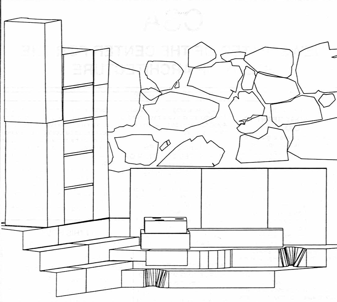
Fig. 1 - The remains of the entrance to the Acropolis from the period prior to the construction
of the Propylaea in 437 B.C. The rough stones of the Mycenaean fortification wall (in black, roughly in the center of
the image) were surveyed with the Rollei MR2 program. The cracks in the regular blocks of the upper level (cyan, blocks
to the left) were surveyed with single-photograph photogrammetry - more correctly called a plane transformation - directly in
AutoCAD®.
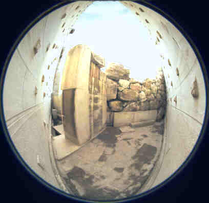
Fig. 2. A view of the Mycenaean fortification wall, showing the stones that were surveyed. Note that the stones of the
fortification wall that lie toward the viewer's right are not included in the drawing. Because of their locations, it was not
possible to obtain enough photographs from different directions to permit accurate survey work. (This image was not included in
the original Newsletter article, and Fig. 1 in the Newsletter was a different drawing.)
For other Newsletter articles concerning the applications of photogrammetry and CAD modeling in archaeology and architectural history, consult the Subject index.
Next Article: Using the MR2 Program and Tolerating Frustration
Table of Contents for the August, 1990 issue of the CSA Newsletter (Vol. III, no. 2)
 Table of Contents for all CSA Newsletter issues on the Web